Intelligent Grid Experimental Facilities
The Intelligent Grid Experimental Facilities at IERC – Tyndall offer a virtual living lab for low-voltage microgrid research, integrating detailed modelling, real-time simulation, and hardware testing. A CIGRE-based low-voltage network model lies at the core of the setup, incorporating distributed energy resources (DERs) such as rooftop photovoltaics, battery storage, heat pumps and electric vehicles. This virtual microgrid model is interfaced with real hardware (inverters, loads, controllers, etc.) via power hardware-in-the-loop (P-HIL) techniques, allowing experiments under realistic grid conditions. The virtual lab enables testing of advanced control and energy-trading algorithms before field deployment, essentially creating a power hardware-in-the-loop living laboratory for future smart homes and buildings.
Virtual Microgrid Model and Lab Development
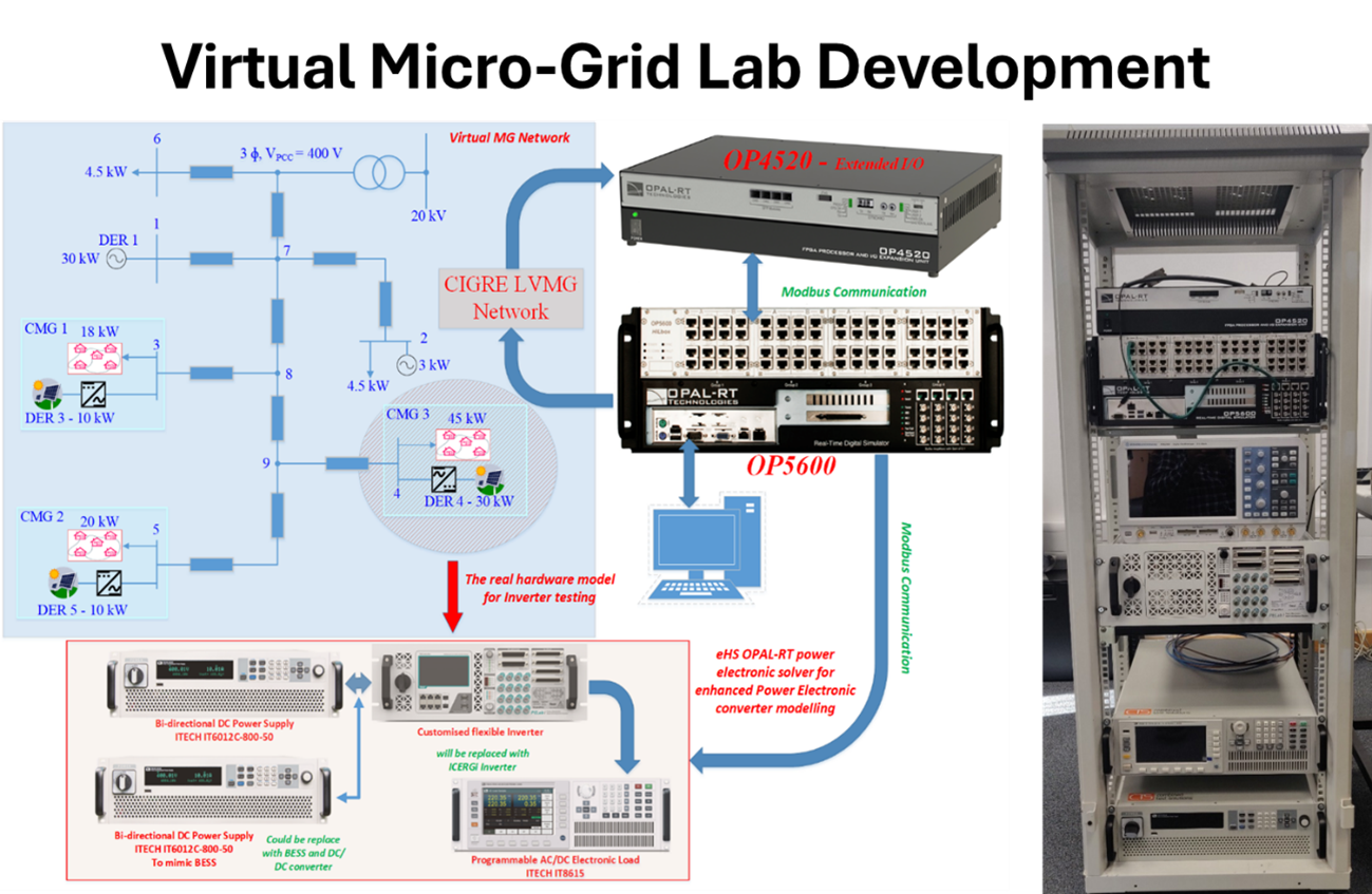
- CIGRE-Based Network Model: The facility’s virtual microgrid is built on an international CIGRE benchmark of a low-voltage distribution network, capturing realistic line impedances and topology. This model includes typical residential and community loads (lighting, appliances) and generation (PV, micro-wind), as well as new DER elements (battery banks, heat-pump loads, EV chargers). Researchers can adjust network parameters or fault conditions in software, while observing physical effects through the lab’s instrumentation.
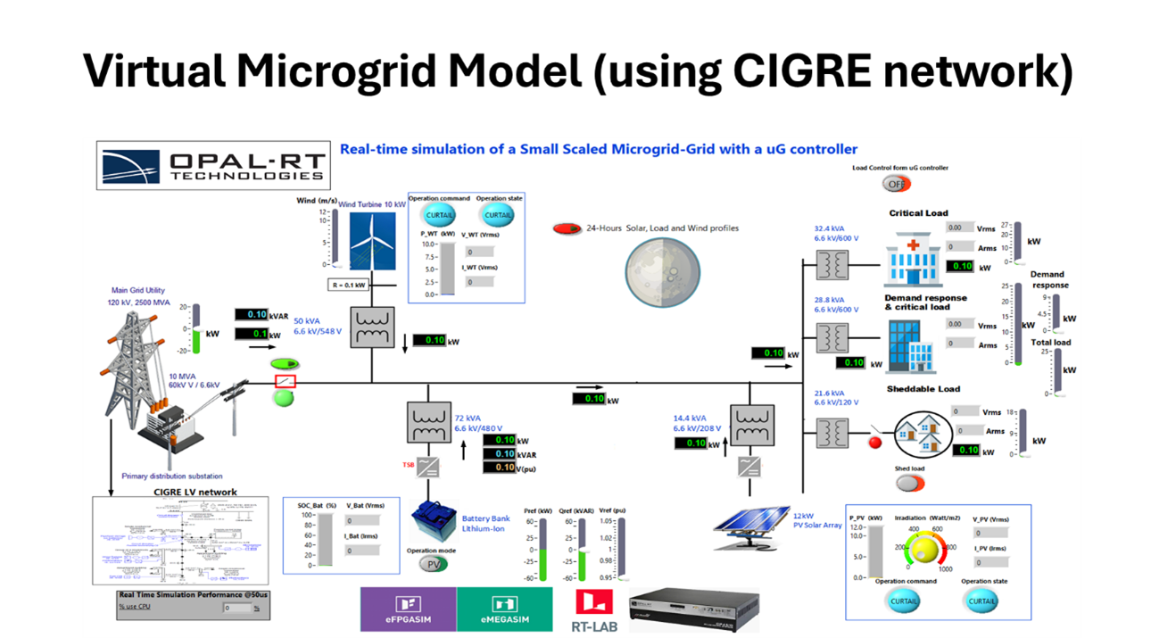
- Super-Home and EV Integration: In partnership projects (e.g., FET-EV, SuHSI), the virtual grid model is populated with super-home Each “super home” is a residential node equipped with high-efficiency DERs (solar panels, home storage, smart inverters) and an EV charger. The smart inverters implement advanced control schemes (including vehicle-to-home/Grid (V2H/V2G) functions) so that homes become active grid participants. By emulating these on the lab’s virtual microgrid, the team can measure impacts on voltage, power quality and market signals in real time. This approach lets engineers rapidly prototype smart home controls and peer-to-peer energy trading models using Hardware-in-the-Loop (HIL) validation before deploying them in actual communities.
- Virtual Living Lab Concept: In this context, the facility acts as a “Virtual Living Lab” – a modular, reconfigurable testbed where a combination of simulated network models and physical hardware represents each element (households, EV chargers, storage units). Control algorithms and management strategies (for example, home energy management systems or grid-support functions) are applied to real controllers and inverters in the loop, and their effects are observed on the network model. This methodology accelerates R&D by enabling closed-loop testing: engineers can tweak controller code or hardware and instantly see system-wide outcomes as if in a real deployment.
Real-Time Simulation and HIL Infrastructure
To support these experiments, the lab is built around high-performance real-time simulators and HIL platforms. Key components include:
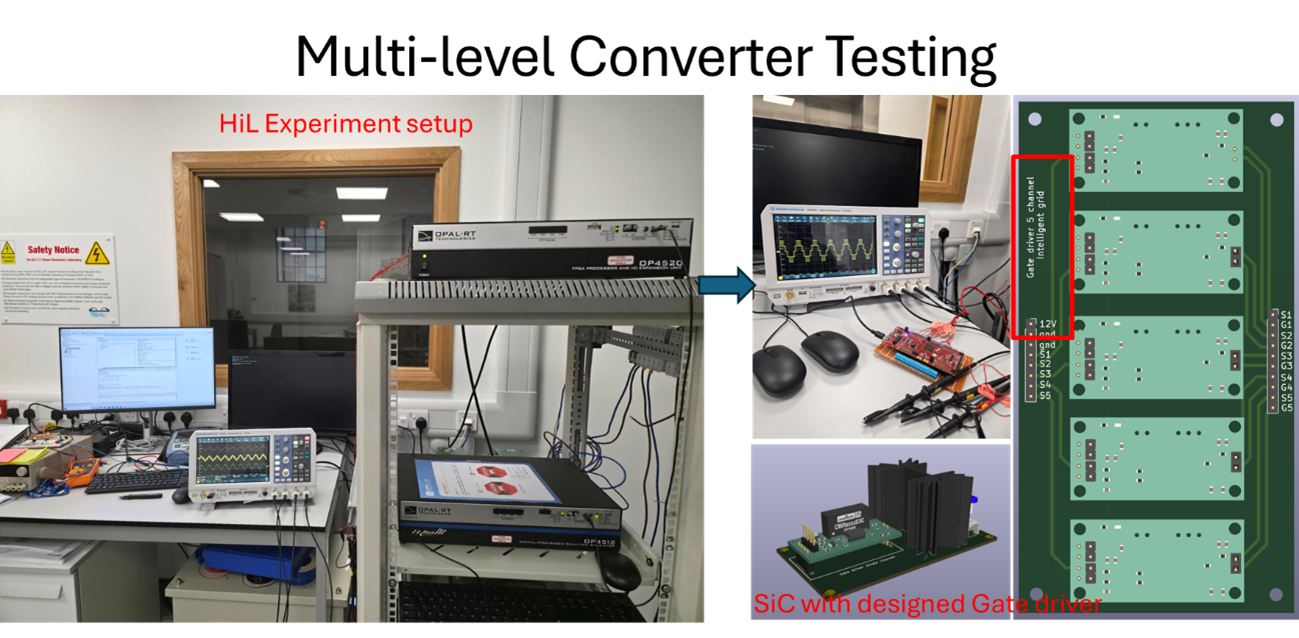
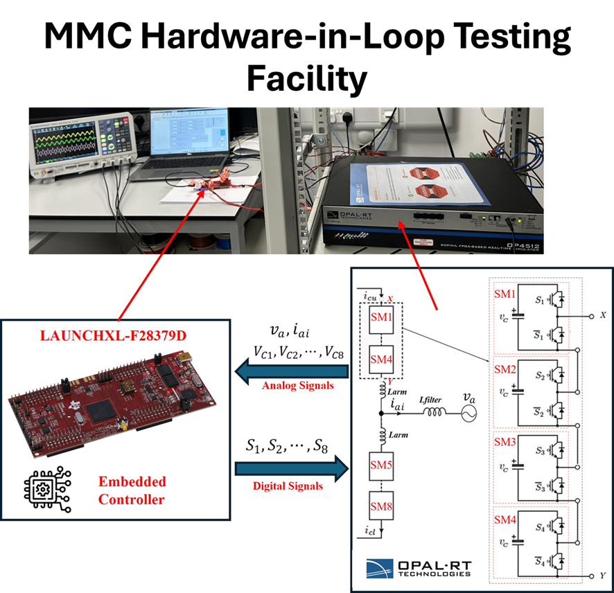
- OPAL-RT Real-Time Simulators (OP4512/OP4520): The backbone of the P-HIL system is OPAL-RT’s hardware, specifically the OP4512 and OP4520 platforms. These rack-mounted simulators combine multi-core Intel Xeon CPUs with Xilinx FPGAs to achieve sub-microsecond simulation time steps. In practice, this means the entire virtual distribution network (power lines, loads, PV systems, etc.) can be emulated with high accuracy while exchanging analog and digital signals with real hardware in real time. For example, a power inverter under test might receive voltage/current signals from the OP4512 and send back PWM gating signals, with the simulator updating grid voltages accordingly in under 10 μs. In short, the OPAL-RT systems enable power hardware-in-the-loop (P-HIL) experiments that faithfully reproduce grid dynamics while hardware converters and loads operate as if on a live network.
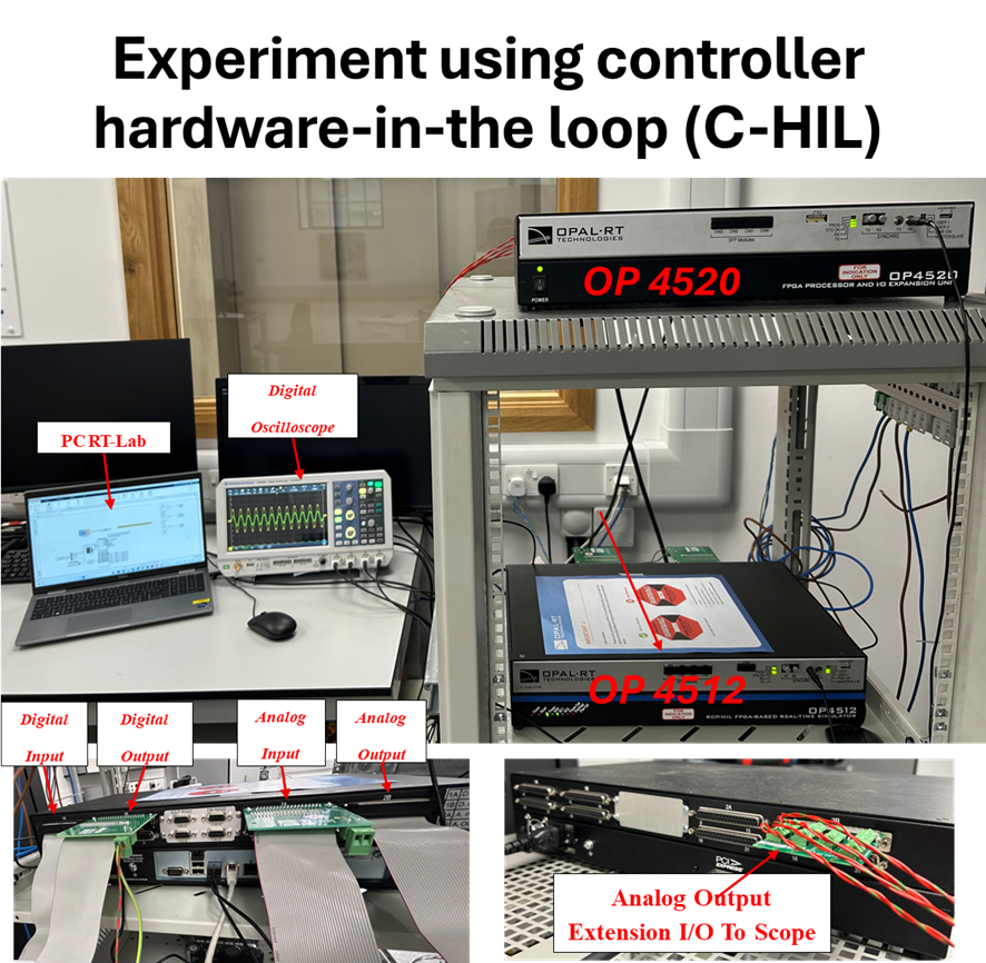
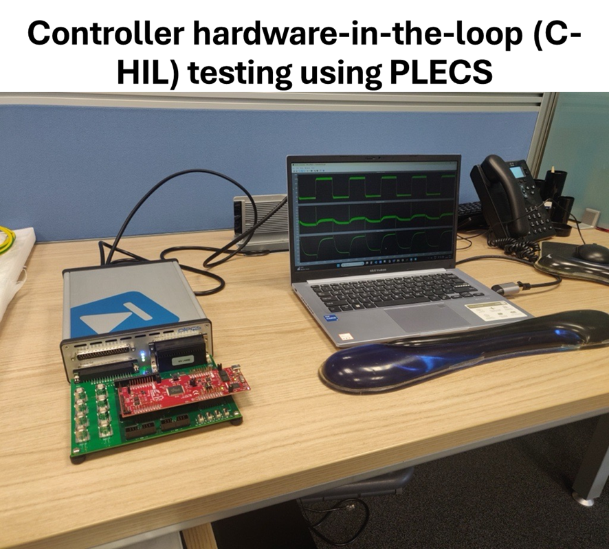
- PLECS RT Box for Controller HIL: In addition to power stage HIL, the lab also supports controller hardware-in-the-loop (C-HIL) Researchers use Plexim’s PLECS RT Box (or similar platforms) to emulate converter power stages, allowing actual microcontroller-based gate-driver boards or control units to be tested as the device-under-test. In this setup, the PLECS RT Box generates the analog voltage/current signals that a real converter’s sensors would see, while capturing the controller’s PWM outputs with nanosecond resolution. This lets the team validate complete control firmware and gate-driver electronics in isolation (e.g. developing a new modulation scheme or protection logic) without building a full power hardware. By pairing OPAL-RT (for power network) with PLECS (for controller), the facility can perform comprehensive HIL cycles: either the controller under test drives a simulated converter, or a real converter drives a simulated grid, as needed.
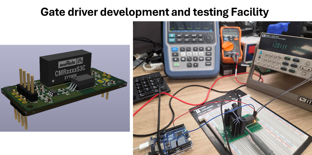
- Gate-Driver and Inverter Testbeds: The lab includes benches for developing and characterising gate-driver circuits. These benches have power supplies, oscilloscopes and safety interlocks to safely test drivers at various gate voltages. Researchers are building custom SiC (silicon carbide) power modules and associated high-voltage gate-driver boards, which are then validated in this environment. By interfacing these converters with the real-time simulators, multi-level inverters (including Modular Multilevel Converters – MMCs) can be tested under controllable grid conditions. MMCs, in particular, are a focus of research given their importance for HVDC links and renewable integration: the lab’s MMC hardware-in-the-loop setup allows exploration of advanced control strategies for these multilevel converters.
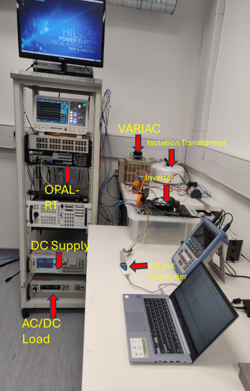
- AC/DC Loads, Variacs, and Power Supplies: Physical load equipment is also integral. Programmable AC loads and DC electronic loads allow realistic demand-side testing. Motorized Variacs (variable auto-transformers) and isolation transformers provide adjustable AC supply rails for testing grid tolerance and grounding schemes. High-power DC supplies simulate battery or EV input conditions. Together, these allow any combination of worst-case or fault-loading scenarios. For instance, to emulate an EV charging session, a controllable DC load can draw a sinusoidal power profile while the simulated grid responds, enabling study of V2G/V2H control strategies.
Key Capabilities and Research Use-Cases
The combination of virtual modelling and hardware facilities empowers a wide range of microgrid and power electronics experiments:
- Inverter and Converter Testing: Any inverter (single-phase or three-phase, two-level or multi-level) can be driven with synthetic waveforms or with the actual grid model. Smart inverter functionality – such as reactive power support, anti-islanding, or grid-forming control – can be evaluated under controlled perturbations. The facility’s ability to simulate grid faults, voltage sags/swells, and harmonics allows thorough verification of inverter compliance and robustness.
- Controller Development (RCP and HIL): Rapid control prototyping (RCP) workflows are supported by the simulators’ FPGA/CPU co-simulation. Controller algorithms developed in MATLAB/Simulink or other environments can be downloaded to the PLECS or OPAL hardware, so that new DSP or FPGA-based controllers can be iteratively tested. Researchers are advancing new control strategies (including AI-based energy management) for both home-energy systems and wider network operation. All such controllers are validated on the virtual lab before any field trials.
- Smart Home/Super Home Scenarios: Using the lab, entire house-energy management systems can be tested. For example, a home equipped with solar, storage and a smart EV charger can be connected to the virtual grid. The researchers can then run scenarios (overnight low-demand, daytime PV surplus, vehicle charging peaks) and verify that the home controller achieves targets (minimising bill or grid impact) while maintaining comfort. The Virtual Living Lab approach means hundreds of such “homes” can be emulated simply by reconfiguring the model, without needing physical houses.
- EV Charging Station Integration: The facility includes infrastructure for studying EV chargers. This includes DC fast-charge simulators and communication modules to test grid interactions (V2G, smart charging, demand response). For instance, by emulating multiple EVs connecting/disconnecting, researchers can see how a local transformer or feeder would be loaded and how smart scheduling algorithms perform.
- Energy Harvester and Speciality Converters: Beyond standard DERs, the lab also tackles niche devices. A dedicated setup for low-power energy harvesters (e.g. vibration or induction harvesters) lets developers test their custom DC/DC converters at scale. These harvesters can be interfaced through the lab’s DC supplies and loads to characterise performance under realistic conditions. Similarly, speciality converters (like high-frequency induction-power topologies) can be benchmarked in the loop with the grid model.

By integrating these capabilities, the Intelligent Grid Experimental Facilities serve both academic research and industrial R&D. The lab’s virtual power hardware-in-the-loop approach significantly shortens design cycles: novel converters or controls are first validated in the virtual lab with full measurement and logging, and only the final versions require costly field prototypes. This accelerates innovation in microgrids, renewable integration and smart home energy systems.